[Japanese |
English(?) ]
2�$B
These following images were taken by using 2-dimensional delay line detector
(Roentdek DLD-40).

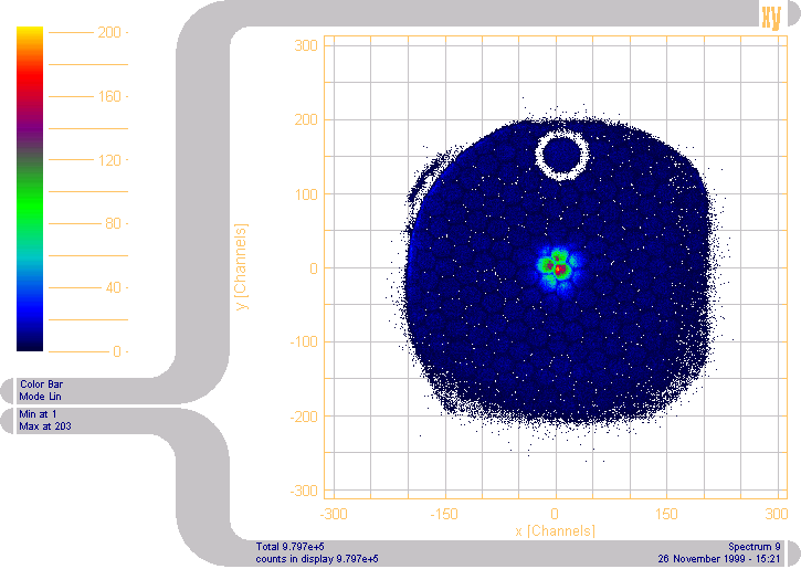
threshold : 3.5V
applied voltages
*MCP front : -2100V
*MCP back : 0V
*Anode Holder : 100V
*Reference wires : 350V
*Collecting (Signal) wires : 400V
Pulse With : W1 = 4.7V , W3-6 = 4.7V

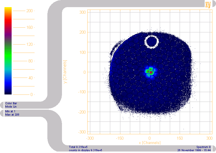
threshold : 3.5V
applied voltages
*MCP front : -2100V
*MCP back : 0V
*Anode Holder : 100V
*Reference wires : 350V
*Collecting (Signal) wires : 400V
Pulse With : W1 = 1.0V , W3-6 = 4.7V

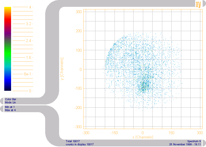
threshold : 3.5V
applied voltages
*MCP front : -2100V
*MCP back : 0V
*Anode Holder : 100V
*Reference wires : 350V
*Collecting (Signal) wires : 400V
Pulse With : W1 = 1.0V , W3-6 = 1.0V

Only this without Am-241 alpha source.
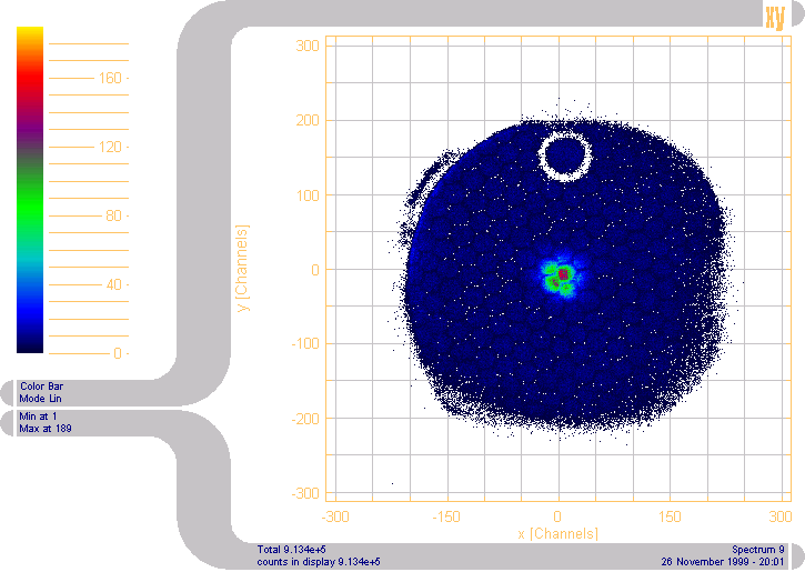
threshold : 3.5V
applied voltages
*MCP front : -2100V
*MCP back : 0V
*Anode Holder : 100V
*Reference wires : 350V
*Collecting (Signal) wires : 400V
Pulse With : W1 = 4.7V , W3-6 = 4.7V

The start signal cable (from MCP fromt) was cut from 6m to 3m.
threshold : 3.5V
applied voltages
*MCP front : -2100V
*MCP back : 0V
*Anode Holder : 100V
*Reference wires : 350V
*Collecting (Signal) wires : 400V
Pulse With : W1 = 4.7V , W3-6 = 4.7V
Notice : The hexagonal shape of these images is a mesh mounted on front of the detector.
�$B$b$C$H>\$7$$�(B Site �$B$K9T$/�(B
�$B2hO-$N%H%C%W�(B�$B$KLa$k�(B
�$BL\�$B$KLa$k�(B


